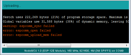
I am getting “espcomm_sync failed” error when trying to upload my ESP. How to resolve this issue?
Introduction
This message indicates issue with uploading ESP module over a serial connection. There are couple of possible causes, that depend on the type of module, if you use separate USB to serial converter, what parameters are selected for upload, etc. As result there is no single answer on the root cause. To find it out you may need to complete couple of troubleshooting steps.
Note: If you are just starting with ESP, to reduce potential issues with uploading, select ESP board with integrated USB to serial converter. This will considerably reduce number of user depended factors or configuration settings that influence upload process.
Example boards with USB to serial converter build in, that will make your initial project development easier, are shown below.
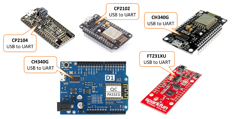
Example boards with integrated USB to serial converter
If you are using a Generic ESP8266 module, separate USB to serial converter and connect them by yourself, please make sure you have the following three things right: 1. Module is provided with enough power, 2. GPIO0, GPIO15 and CH_PD are connected using pull up / pull down resistors, 3. Module is put into boot loader mode.
For specific details please refer to section on Generic ESP8266 modules. Example modules without USB to serial converter on board are shown below.
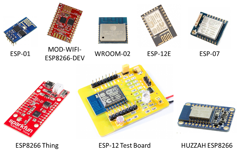
Example ESP8266 modules without USB to serial converter
Initial Checks
In order to troubleshoot “espcomm_sync failed” error, please proceed step by step through the checklist below. This list is organized starting with most common and simple to more complex issues.
- Start with reading exact message displayed in debug window of Arduino IDE. In many cases it provides direct information where the issue is.
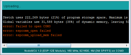
“espcomm_open failed” error
For instance message above suggests that Arduino IDE is unable to open a serial port COM3. Check if you have selected port where your module is connected to.
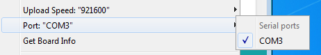
Serial port selection
- If a module is connected to the serial port but not responding as a valid ESP8266 device, the message will read slightly different (see below). If you have other modules connected to your PC, make sure that you are uploading code to ESP8266 and not to e.g. Arduino UNO.
Serial port selection
- To have your PC talking to ESP, select exact ESP type in upload menu. If selection is incorrect then the upload may fail.
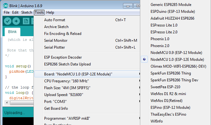
Board selection
Basing on selected board type, Arduino IDE will apply specific “reset method” to enter the board into boot loading mode. Reset methods are board specific. Some boards do not have the h/w in place to support reset by Arduino IDE. If this is the case, you need to enter such board into boot loading mode manually.
- Upload may be also failing due to too high speed. If you have long or poor quality USB cable, try reducing selection under Upload Speed.
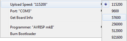
Serial speed selection
Advanced Checks
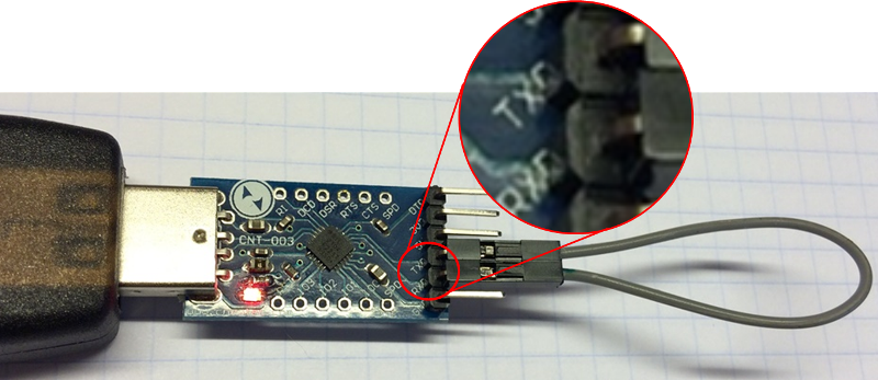
- If you are still facing issues, test if module is indeed entering the boot loading mode. You can do it by connecting secondary USB to serial converter and checking the message displayed. Attach RX and GND pins of converter to TX and GND pin of ESP as shown on example below (get fzz source).
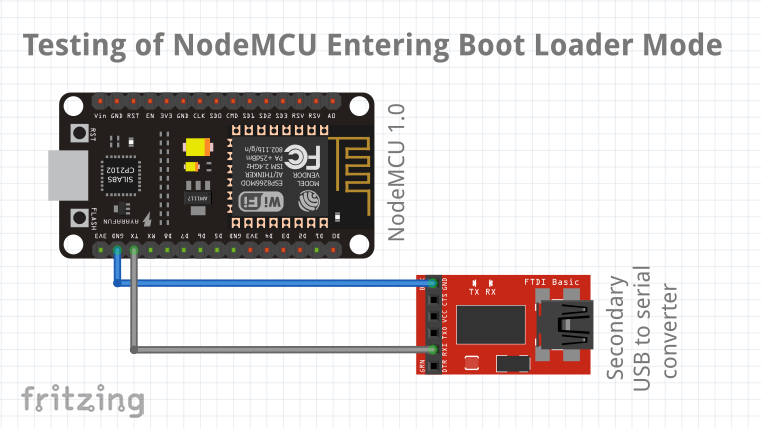
Secondary USB to serial converter hookup
Then open a terminal at 74880 baud, and look what message is reported when ESP is being reset for programming. Correct message looks as follows:
ets Jan 8 2013,rst cause:2, boot mode:(1,7)
If you see similar message but different values then decode them using Boot Messages and Modes. The key information is contained in first digit / three right-most bits of the boot mode message as shown below.
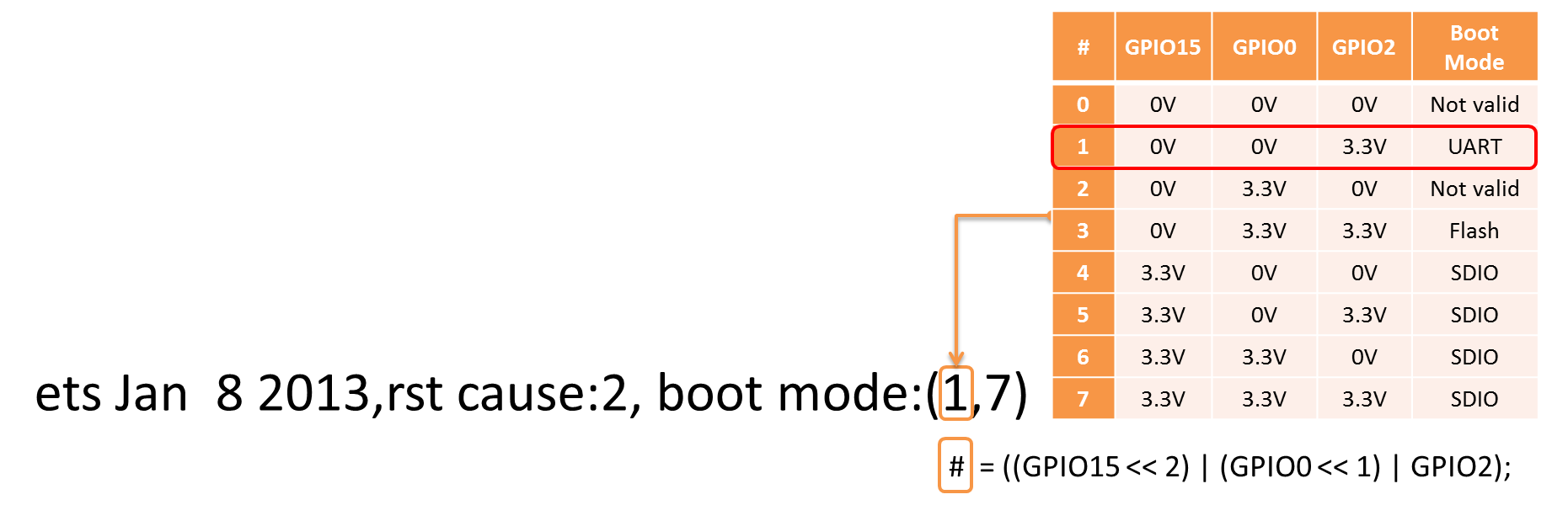
Decoding of boot mode
For instance message boot mode (3,3) indicates that pins GPIO2 and
GPIO0 are set HIGH and GPIO15 is set LOW. This is configuration for
normal
operation of
module (to execute application from flash), not for boot
loading
(flash programming).
Note: Without having this step right you will not be able to upload your module over a serial port.
- You have confirmed that module is in boot loading mode but upload still fails. If you are using external USB to serial converter, then check if it operates correctly by looping it back. This is quite simple check. Just connect TX and RX of your converter together like on picture below. Then open Serial Monitor and type some characters. If everything is fine, then you should see what you type immediately printed back on the monitor. For an ESP with USB to serial converter on board, this check may involve breaking some PCB traces. I would not do it unless being desperate. Instead try steps below.
USB to serial converter loop back
- Next step to try, if not done already, is checking detailed debug messages. Go to File > Preferences, enable Show verbose output during: upload and try uploading again. For successful upload this log should look similar to example shown below:
C:\Users\Krzysztof\AppData\Local\Arduino15\packages\esp8266\tools\esptool\0.4.8/esptool.exe -vv -cd ck -cb 115200 -cp COM3 -ca 0x00000 -cf C:\Users\KRZYSZ~1\AppData\Local\Temp\build7e44b372385012e74d64fb272d24b802.tmp/Blink.ino.bin esptool v0.4.8 - (c) 2014 Ch. Klippel <ck@atelier-klippel.de> setting board to ck setting baudrate from 115200 to 115200 setting port from COM1 to COM3 setting address from 0x00000000 to 0x00000000 espcomm_upload_file espcomm_upload_mem setting serial port timeouts to 1000 ms opening bootloader resetting board trying to connect flush start setting serial port timeouts to 1 ms setting serial port timeouts to 1000 ms flush complete espcomm_send_command: sending command header espcomm_send_command: sending command payload read 0, requested 1 trying to connect flush start setting serial port timeouts to 1 ms setting serial port timeouts to 1000 ms flush complete espcomm_send_command: sending command header espcomm_send_command: sending command payload espcomm_send_command: receiving 2 bytes of data espcomm_send_command: receiving 2 bytes of data espcomm_send_command: receiving 2 bytes of data espcomm_send_command: receiving 2 bytes of data espcomm_send_command: receiving 2 bytes of data espcomm_send_command: receiving 2 bytes of data espcomm_send_command: receiving 2 bytes of data espcomm_send_command: receiving 2 bytes of data Uploading 226368 bytes from to flash at 0x00000000 erasing flash size: 037440 address: 000000 first_sector_index: 0 total_sector_count: 56 head_sector_count: 16 adjusted_sector_count: 40 erase_size: 028000 espcomm_send_command: sending command header espcomm_send_command: sending command payload setting serial port timeouts to 15000 ms setting serial port timeouts to 1000 ms espcomm_send_command: receiving 2 bytes of data writing flash .............................................................................................................................................................................................................................. starting app without reboot espcomm_send_command: sending command header espcomm_send_command: sending command payload espcomm_send_command: receiving 2 bytes of data closing bootloader flush start setting serial port timeouts to 1 ms setting serial port timeouts to 1000 ms flush complete
Upload log may be longer depending on number of connection attempts made by esptool. Analyze it for any anomalies to configuration you have selected in Arduino IDE, like different serial port, reset method, baud rate, etc. Resolve all noted differences.
Reset Methods
If you got to this point and still see espcomm_sync failed, then now
you need to bring in the heavy guns.
Connect scope or logic analyzer to GPIO0, RST and RXD pins of the ESP to check what’s happening.
Then compare your measurements with wave-forms collected for circuits below. They document two standard methods of resetting ESP8266 for upload, that you can select in Arduino IDE - ck and nodemcu.
Ck
Circuit below has been prepared to collect wave-forms for ck reset method (get fzz source). It is simpler than for nodemcu reset and therefore often used to wire up generic ESP modules on a breadboard. Check it against your wiring when comparing your measurements against wave-forms below.
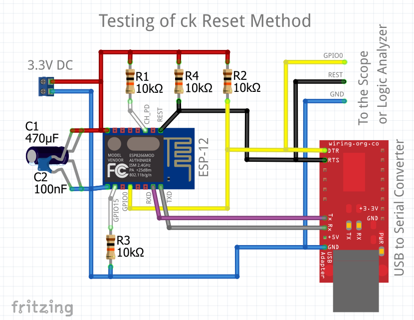
Sample circuit to check ck method
The following wave-forms below show voltage signals on GPIO0 and RST pins of the ESP board when uploading the firmware.
Close up of ck reset method signal sequence at the beginning of upload is shown below.
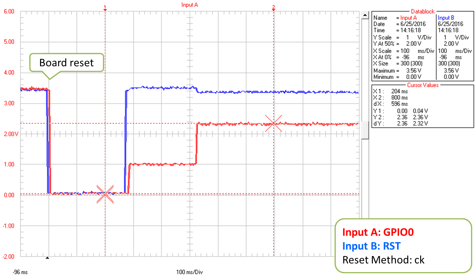
Reset Method: ck, close up at the beginning of upload
Next picture shows complete upload of Blink.ino example at 921600 baud. This is quite high speed, so the upload takes only about 8s.
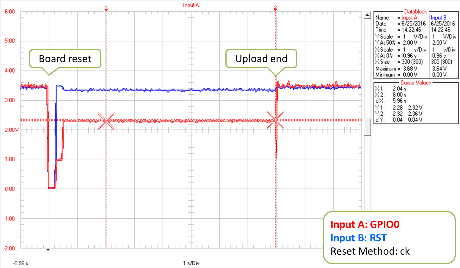
Reset Method: ck, complete upload
Please note that when esptool is not able to initialize upload at the first time, then it retries reset procedure. Case of one such retry is shown on wave-form below.
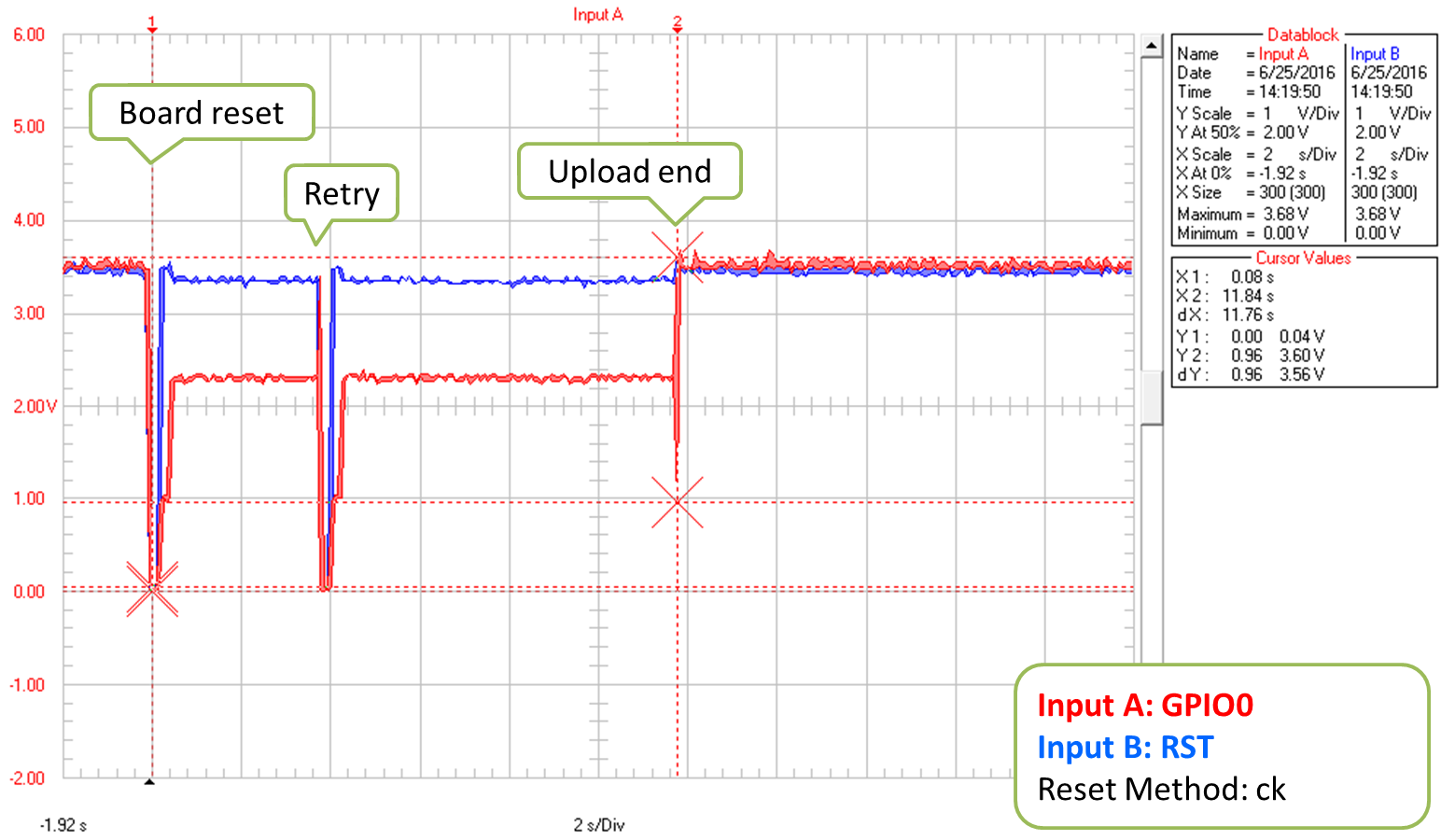
Reset Method: ck, complete upload
Each retry is reported in upload log as follows:
resetting board
trying to connect
    flush start
    setting serial port timeouts to 1 ms
    setting serial port timeouts to 1000 ms
    flush complete
    espcomm_send_command: sending command header
    espcomm_send_command: sending command payload
    read 0, requested 1
Presented circuit has one important limitation when it comes to work with Arduino IDE. After opening Serial Monitor (Ctrl-Shift-M), both RTS and DTR lines are permanently pulled down. As RTS line is connected to REST input of ESP, the module is hold in reset state / not able to run. Therefore after uploading module, you need to disconnect both lines or use different serial terminal program that is not pulling down RTS and DTR lines. Otherwise the module will get stuck waiting for releasing the REST signal and you will see nothing on the Serial Monitor.
As for different serial terminal program you can check Arduino IDE add-on Serial Monitor for ESP8266 developed by user [@mytrain](https://github.com/mytrain) and discussed in #1360.
If you prefer external terminal program, then for Windows users we can recommend free and handy Termite.
Nodemcu
Nodemcu reset method is named after NodeMCU board where it has been introduced for the first time. It overcomes limitations with handling of RTS and DTR lines discussed for ck reset method above.
Sample circuit to measure wave-form is shown below (get fzz source).
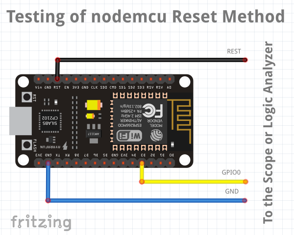
Sample circuit to check nodemcu reset method
Close up of voltage signals on GPIO0 and RST pins at the beginning of firmware upload is shown below.
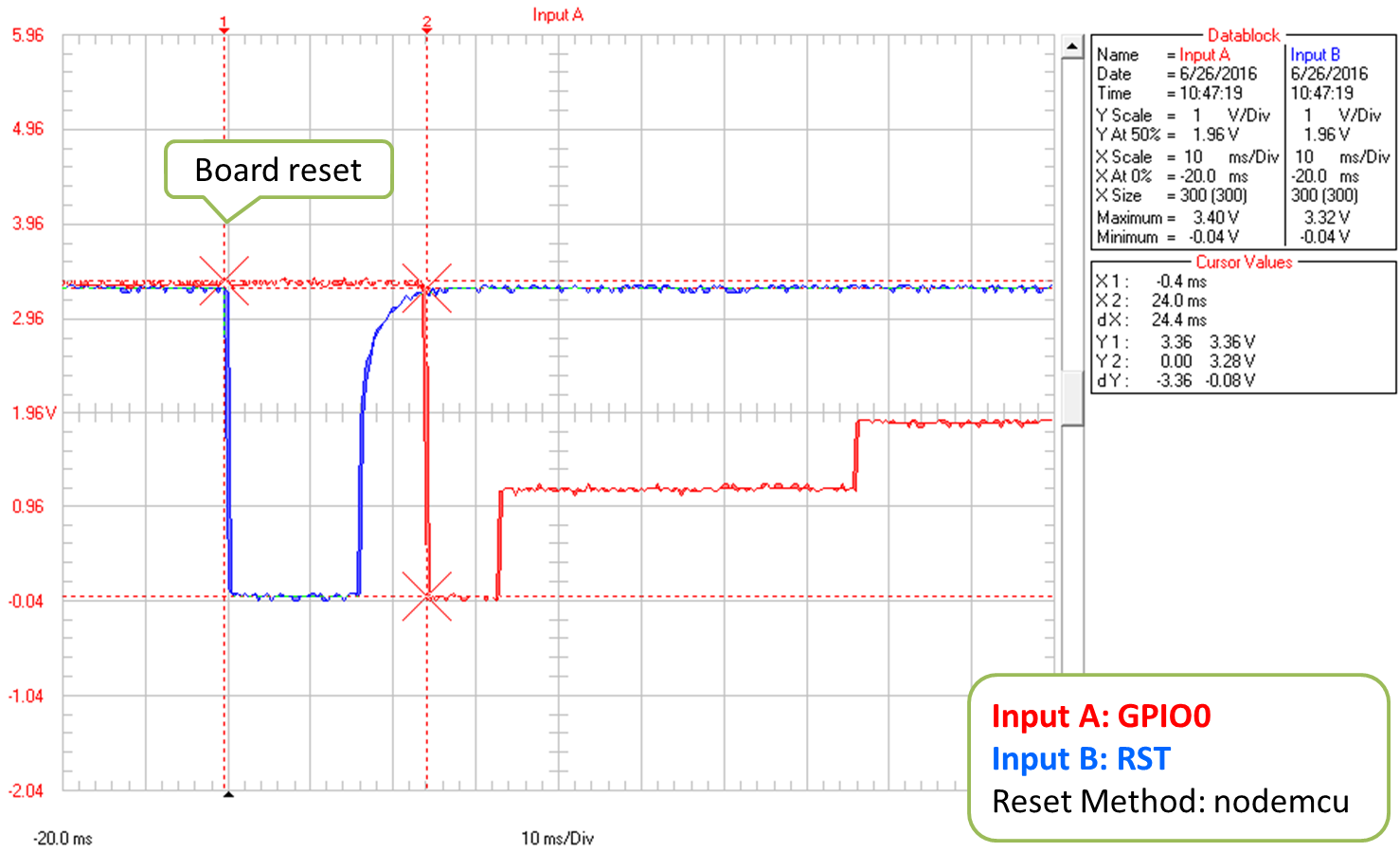
Reset Method: nodemcu, close up at the beginning of upload
Please note that the reset sequence is about 10x shorter comparing to ck reset (about 25ms vs. 250ms).
Next picture covers complete upload of Blink.ino example at 921600 baud. Except for difference of the reset signal sequence, the complete upload looks similar to that of ck.
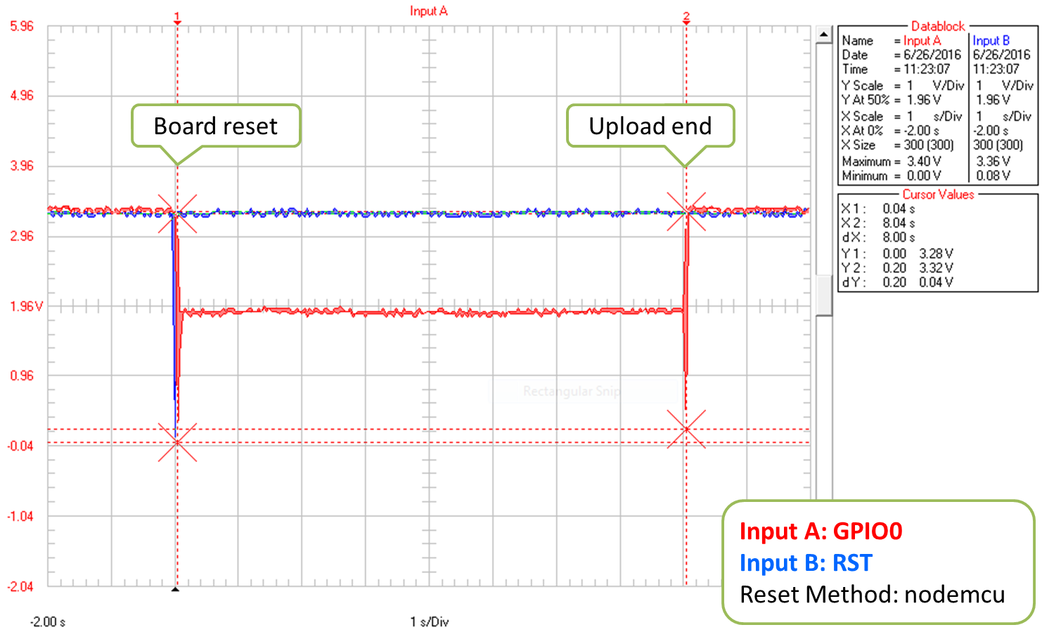
Reset Method: nodemcu, complete upload
A sample wave-form below shows another upload of Blink.ino example at 921600 baud, but with two reset retries.
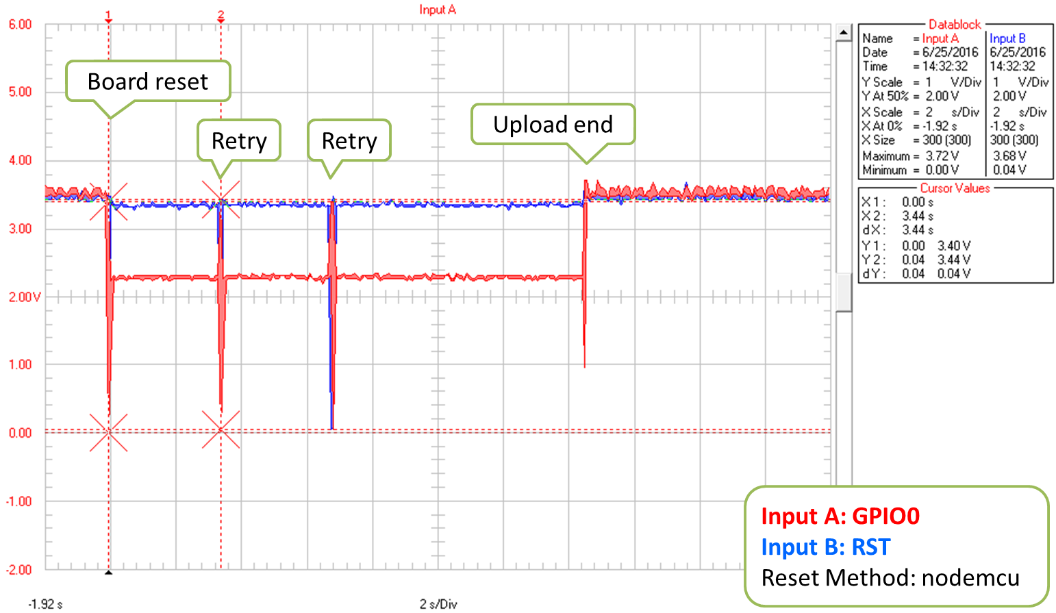
Reset Method: nodemcu, reset retries
If you are interested how noodemcu reset method is implemented, then check circuit below. As indicated it does not pull to ground RTS and DTR lines once you open Serial Monitor in Arduino IDE.
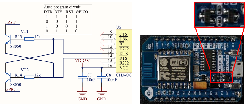
Implementation of noodemcu reset
It consists of two transistors and resistors that you can locate on NodeMCU board on right. On left you can see complete circuit and the truth table how RTS and DTR signals of the serial interface are translated to RST and GPIO0 on the ESP. For more details please refer to nodemcu repository on GitHub.
I’m Stuck
Hopefully at this point you were able to resolve espcomm_sync failed issue and now enjoy quick and reliable uploads of your ESP modules.
If this is still not the case, then review once more all discussed steps in the checklist below.
Initial Checks
- [ ] Is your module connected to serial port and visible in IDE?
- [ ] Is connected device responding to IDE? What is exact message in debug window?
- [ ] Have you selected correct ESP module type in Board menu? What is the selection?
- [ ] Have you tried to reduce upload speed? What speeds have you tried?
Advanced Checks
- [ ] What message is reported by ESP at 74880 baud when entering boot loading mode?
- [ ] Have you checked your USB to serial converter by looping it back? What is the result?
- [ ] Is your detailed upload log consistent with settings in IDE? What is the log?
Reset Method
- [ ] What reset method do you use?
- [ ] What is your connection diagram? Does it match diagram in this FAQ?
- [ ] What is your wave-form of board reset? Does it match wave-form in this FAQ?
- [ ] What is your wave-form of complete upload? Does it match wave-form in this FAQ?
Software
- [ ] Do you use the latest stable version of esp8266 / Arduino? What is it?
- [ ] What is the name and version of your IDE and O/S?
If you are stuck at certain step, then post this list on ESP8266 Community Forum asking for support.
Conclusion
With variety of available ESP8266 modules and boards, as well as possible connection methods, troubleshooting of upload issues may take several steps.
If you are a beginner, then use boards with integrated power supply and USB to serial converter. Check carefully message in debug window and act accordingly. Select your exact module type in IDE and try to adjust upload speed. Check if board is indeed entering boot loading mode. Check operation of your USB to serial converter with loop back. Analyze detailed upload log for inconsistencies with IDE settings.
Verify your connection diagram and wave-form for consistency with selected reset method.
If you get stuck, then ask community for support providing summary of all completed checks.
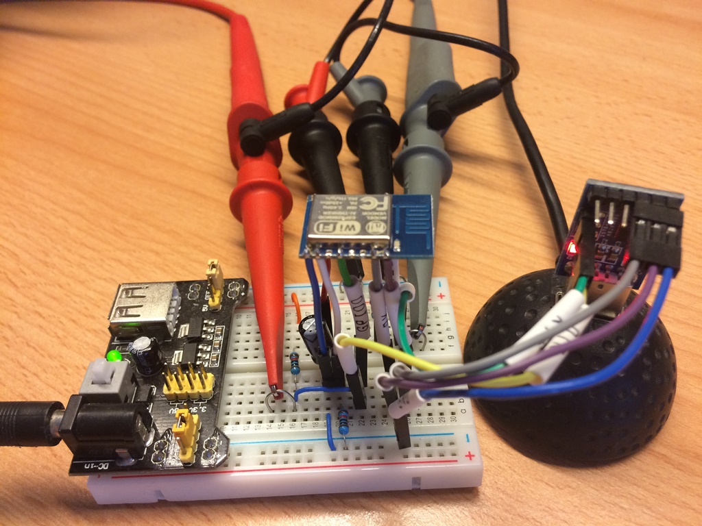
Test stand used during checking of ck reset method
Test stand used for checking of ck reset method is shown above.
No any ESP module has been harmed during preparation of this FAQ item.