OTA Updates
Introduction
OTA (Over the Air) update is the process of loading the firmware to ESP module using Wi-Fi connection rather than a serial port. Such functionality became extremely useful in case of limited or no physical access to the module.
OTA may be done using:
Arduino IDE option is intended primarily for software development phase. The two other options would be more useful after deployment, to provide module with application updates manually with a web browser, or automatically using a http server.
In any case, the first firmware upload has to be done over a serial port. If the OTA routines are correctly implemented in a sketch, then all subsequent uploads may be done over the air.
By default there is no imposed security on OTA process. It is up to developer to ensure that updates are allowed only from legitimate / trusted sources. Once the update is complete, the module restarts, and the new code is executed. The developer should ensure that the application running on the module is shut down and restarted in a safe manner. Chapters below provide additional information regarding security and safety of OTA process.
Security Disclaimer
No guarantees as to the level of security provided for your application by the following methods is implied. Please refer to the GNU LGPL license associated for this project for full disclaimers. If you do find security weaknesses, please don’t hesitate to contact the maintainers or supply pull requests with fixes. The MD5 verification and password protection schemes are already known as supplying a very weak level of security.
Basic Security
The module has to be exposed wirelessly to get it updated with a new sketch. That poses chances of module being violently hacked and loaded with some other code. To reduce likelihood of being hacked consider protecting your uploads with a password, selecting certain OTA port, etc.
Check functionality provided with ArduinoOTA library that may improve security:
void setPort(uint16_t port);
void setHostname(const char* hostname);
void setPassword(const char* password);
Certain protection functionality is already built in and do not require any additional coding by developer. ArduinoOTA and espota.py use Digest-MD5 to authenticate upload. Integrity of transferred data is verified on ESP side using MD5 checksum.
Make your own risk analysis and depending on application decide what library functions to implement. If required, consider implementation of other means of protection from being hacked, e.g. exposing module for uploads only according to specific schedule, trigger OTA only be user pressing dedicated “Update” button wired to ESP, etc.
Advanced Security - Signed Updates
While the above password-based security will dissuade casual hacking attempts, it is not highly secure. For applications where a higher level of security is needed, cryptographically signed OTA updates can be required. It uses SHA256 hashing in place of MD5 (which is known to be cryptographically broken) and RSA-2048 bit level encryption to guarantee only the holder of a cryptographic private key can generate code accepted by the OTA update mechanisms.
These are updates whose compiled binary are signed with a private key (held by the developer) and verified with a public key (stored in the application and available for all to see). The signing process computes a hash of the binary code, encrypts the hash with the developer’s private key, and appends this encrypted hash to the binary that is uploaded (via OTA, web, or HTTP server). If the code is modified or replaced in any way by anyone by the developer with the key, the hash will not match and the ESP8266 will reject the upload and not accept it.
Cryptographic signing only protects against tampering of binaries delivered OTA. If someone has physical access they will always be able to flash the device over the serial port. Signing also does not encrypt anything but the hash (so that it can’t be modified), so this does not provide protection for code inside the device. Again, if a user has physical access they can read out your program.
Securing your private key is paramount. The same private/public keypair needs to be used to sign binaries as the original upload. Loss of the private key associated with a binary means that you will not be able to OTA to update any of your devices in the field. Alternatively, if the private key is copied, then the copy can be used to sign binaries which will be accepted.
Signed Binary Format
The format of a signed binary is compatible with the standard binary format, and can be uploaded to a non-signed ESP8266 via serial or OTA without any conditions. Note, however, that once an unsigned OTA app is overwritten by this signed version, further updates will require signing.
As shown below, the signed hash is appended to the unsigned binary followed by the total length of the signed hash (i.e. if the signed hash was 64 bytes, then this uint32 will contain 64). This format allows for extensibility (such as adding in a CA-based validation scheme allowing multiple signing keys all based off of a trust anchor), and pull requests are always welcome.
NORMAL-BINARY <SIGNED HASH> <uint32 LENGTH-OF-SIGNING-DATA-INCLUDING-THIS-32-BITS>
Signed Binary Prequisites
OpenSSL is required to run the standard signing steps, and should be available on any UNIX-like or Windows system. As usual, the latest stable version of OpenSSL is recommended.
Signing requires the generation of an RSA-2048 key (other bit lengths are supported as well, but 2048 is a good selection today) using any appropriate tool. The following lines will generate a new public/private keypair. Run them in the sketch directory:
openssl genrsa -out private.key 2048
openssl rsa -in private.key -outform PEM -pubout -out public.key
Automatic Signing – Only available on Linux and Mac
The simplest way of implementing signing is to use the automatic mode, which is only possible on Linux and Mac presently due to missing tools under Windows. This mode uses the IDE to configure the source code to enable sigining verification with a given public key, and signs binaries as part of the standard build process using a given public key.
To enable this mode, just include private.key and public.key in the sketch .ino directory. The IDE will call a helper script (tools/signing.py) before the build begins to create a header to enable key validation using the given public key, and after the build process to actually do the signing, generating a sketch.bin.signed file. When OTA is enabled (ArduinoOTA, Web, or HTTP) the binary will only accept signed updates automatically.
When the signing process starts, the message:
Enabling binary signing
Will appear in the IDE window before a compile is launched, and at the completion of the build the signed binary file well be displayed in the IDE build window as:
Signed binary: /full/path/to/sketch.bin.signed
If you receive either of the following messages in the IDE window, the signing was not completed and you will need to verify the public.key and private.key:
Not enabling binary signing
... or ...
Not signing the generated binary
Manual Signing Binaries
Users may also manually sign executables and require the OTA process to verify their signature. In the main code, before enabling any update methods, add the call:
<in globals>
BearSSL::PublicKey signPubKey( ... key contents ... );
BearSSL::HashSHA256 hash;
BearSSL::SigningVerifier sign( &signPubKey );
...
<in setup()>
Update.installSignature( &hash, &sign );
The above snipped creates a BearSSL public key, a SHA256 hash verifier, and tells the Update object to use them to validate any updates it receives from any method.
Compile the sketch normally and, once a .bin file is available, sign it using the signer script:
<ESP8266ArduioPath>/tools/signing.py --mode sign --privatekey <path-to-private.key> --bin <path-to-unsigned-bin> --out <path-to-signed-binary>
Safety
OTA process takes ESP’s resources and bandwidth during upload. Then module is restarted and a new sketch executed. Analyse and test how it affects functionality of existing and new sketch.
If ESP is placed in remote location and controlling some equipment, you should put additional attention what happens if operation of this equipment is suddenly interrupted by update process. Therefore, decide how to put this equipment into safe state before starting the update. For instance, your module may be controlling a garden watering system in a sequence. If this sequence is not properly shut down and a water valve left open, your garden may be flooded.
The following functions are provided with ArduinoOTA library and intended to handle functionality of your application during specific stages of OTA, or on an OTA error:
void onStart(OTA_CALLBACK(fn));
void onEnd(OTA_CALLBACK(fn));
void onProgress(OTA_CALLBACK_PROGRESS(fn));
void onError(OTA_CALLBACK_ERROR (fn));
OTA Basic Requirements
Flash chip size should be able to hold the old sketch (currently running) and the new sketch (OTA) at the same time.
Keep in mind that the File system and EEPROM for example needs space too (one time) see Flash layout.
ESP.getFreeSketchSpace();
can be used for checking the free space for the new sketch.
For overview of memory layout, where new sketch is stored and how it is copied during OTA process, see Update process - memory view.
The following chapters provide more details and specific methods of doing OTA.
Arduino IDE
Uploading modules wirelessly from Arduino IDE is intended for the following typical scenarios: - during firmware development as a quicker alternative to loading over a serial, - for updating small quantity of modules, - only if modules are available on the same network as the computer with Arduino IDE.
Requirements
- The ESP and the computer must be connected to the same network.
Application Example
Instructions below show configuration of OTA on NodeMCU 1.0 (ESP-12E Module) board. You can use any other board assuming that it meets requirements described above. This instruction is valid for all operating systems supported by Arduino IDE. Screen captures have been made on Windows 7 and you may see small differences (like name of serial port), if you are using Linux and MacOS.
Before you begin, please make sure that you have the following s/w installed:
Arduino IDE 1.6.7 or newer - https://www.arduino.cc/en/Main/Software
esp8266/Arduino platform package 2.0.0 or newer - for instructions follow https://github.com/esp8266/Arduino#installing-with-boards-manager
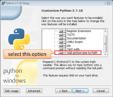
Python 2.7 - https://www.python.org/
Note: Windows users should select “Add python.exe to Path” (see below – this option is not selected by default).
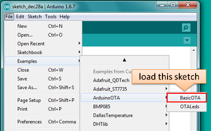
Now prepare the sketch and configuration for the upload over a serial port.
Start Arduino IDE and load sketch BasicOTA.ino available under File > Examples > ArduinoOTA
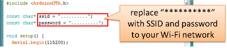
Update SSID and password in the sketch, so the module can join your Wi-Fi network
Configure upload parameters as below (you may need to adjust configuration if you are using a different module):
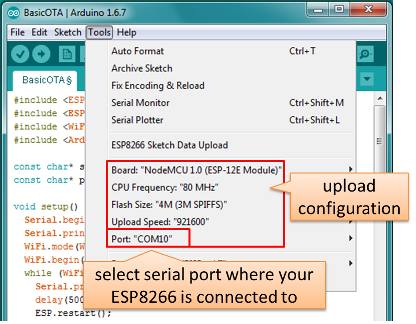
Note: Depending on version of platform package and board you have, you may see
Upload Using:in the menu above. This option is inactive and it does not matter what you select. It has been left for compatibility with older implementation of OTA and finally removed in platform package version 2.2.0.
Upload the sketch (Ctrl+U). Once done, open Serial Monitor (Ctrl+Shift+M) and check if module has joined your Wi-Fi network:
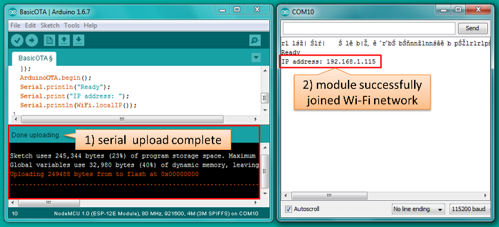
Note: ESP module should be reset after serial upload. Otherwise subsequent steps will not work. Reset may be done automatically for you after opening serial monitor as visible on the screenshot above. It depends on how you have DTR and RTS wired from USB-Serial converter to the ESP. If reset is not done automatically, then do it by pressing reset button or manually cycling the power. For more details why this should be done please refer to FAQ regarding ESP.restart().
Only if module is connected to network, after a couple of seconds, the esp8266-ota port will show up in Arduino IDE. Select port with IP address shown in the Serial Monitor window in previous step:
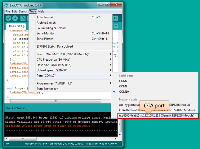
Note: If OTA port does not show up, exit Arduino IDE, open it again and check if port is there. If it does not help, check your firewall and router settings. OTA port is advertised using mDNS service. To check if port is visible by your PC, you can use application like Bonjour Browser.
Now get ready for your first OTA upload by selecting the OTA port:
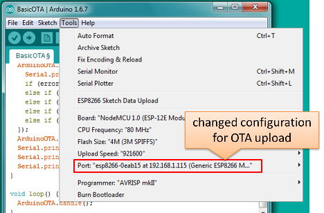
Note: The menu entry
Upload Speed:does not matter at this point as it concerns the serial port. Just left it unchanged.If you have successfully completed all the above steps, you can upload (Ctrl+U) the same (or any other) sketch over OTA:
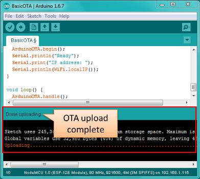
Note: To be able to upload your sketch over and over again using OTA, you need to embed OTA routines inside. Please use BasicOTA.ino as an example.
Password Protection
Protecting your OTA uploads with password is really straightforward. All you need to do, is to include the following statement in your code:
ArduinoOTA.setPassword((const char *)"123");
Where 123 is a sample password that you should replace with your own.
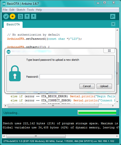
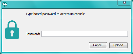
Before implementing it in your sketch, it is a good idea to check how it works using BasicOTA.ino sketch available under File > Examples > ArduinoOTA. Go ahead, open BasicOTA.ino, uncomment the above statement that is already there, and upload the sketch. To make troubleshooting easier, do not modify example sketch besides what is absolutely required. This is including original simple 123 OTA password. Then attempt to upload sketch again (using OTA). After compilation is complete, once upload is about to begin, you should see prompt for password as follows:
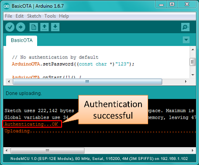
Enter the password and upload should be initiated as usual with the only difference being Authenticating...OK message visible in upload log.
You will not be prompted for a reentering the same password next time. Arduino IDE will remember it for you. You will see prompt for password only after reopening IDE, or if you change it in your sketch, upload the sketch and then try to upload it again.
Please note, it is possible to reveal password entered previously in Arduino IDE, if IDE has not been closed since last upload. This can be done by enabling Show verbose output during: upload in File > Preferences and attempting to upload the module.
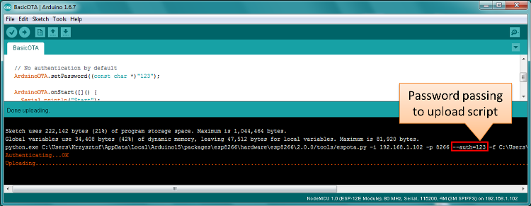
The picture above shows that the password is visible in log, as it is passed to espota.py upload script.
Another example below shows situation when password is changed between uploads.
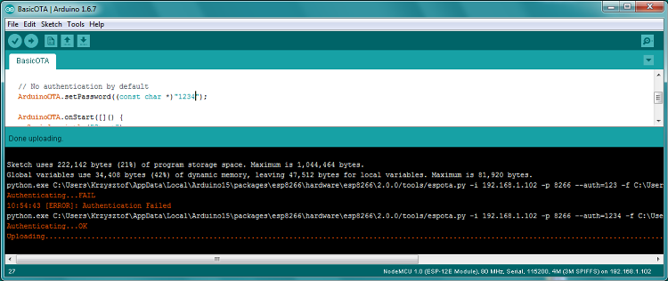
When uploading, Arduino IDE used previously entered password, so the upload failed and that has been clearly reported by IDE. Only then IDE prompted for a new password. That was entered correctly and second attempt to upload has been successful.
Troubleshooting
If OTA update fails, first step is to check for error messages that may be shown in upload window of Arduino IDE. If this is not providing any useful hints, try to upload again while checking what is shown by ESP on serial port. Serial Monitor from IDE will not be useful in that case. When attempting to open it, you will likely see the following:
This window is for Arduino Yún and not yet implemented for esp8266/Arduino. It shows up because IDE is attempting to open Serial Monitor using network port you have selected for OTA upload.
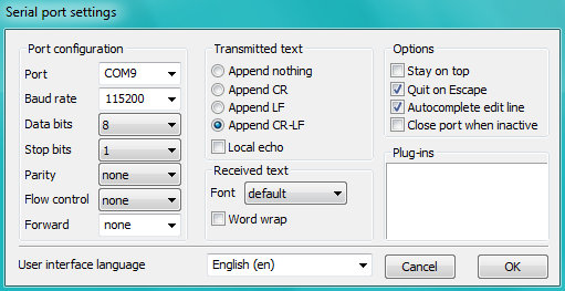
Instead you need an external serial monitor. If you are a Windows user check out Termite. This is handy, slick and simple RS232 terminal that does not impose RTS or DTR flow control. Such flow control may cause issues if you are using respective lines to toggle GPIO0 and RESET pins on ESP for upload.
Select COM port and baud rate on external terminal program as if you were using Arduino Serial Monitor. Please see typical settings for Termite below:
Then run OTA from IDE and look what is displayed on terminal. Successful ArduinoOTA process using BasicOTA.ino sketch looks like below (IP address depends on your network configuration):
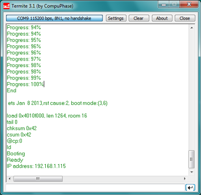
If upload fails you will likely see errors caught by the uploader, exception and the stack trace, or both.
Instead of the log as on the above screen you may see the following:
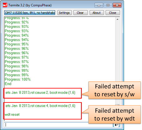
If this is the case, then most likely ESP module has not been reset after initial upload using serial port.
The most common causes of OTA failure are as follows:
- not enough physical memory on the chip (e.g. ESP01 with 512K flash memory is not enough for OTA).
- too much memory declared for SPIFFS so new sketch will not fit between existing sketch and SPIFFS – see Update process - memory view.
- too little memory declared in Arduino IDE for your selected board (i.e. less than physical size).
- not resetting the ESP module after initial upload using serial port.
For more details regarding flash memory layout please check File system. For overview where new sketch is stored, how it is copied and how memory is organized for the purpose of OTA see Update process - memory view.
Web Browser
Updates described in this chapter are done with a web browser that can be useful in the following typical scenarios:
- after application deployment if loading directly from Arduino IDE is inconvenient or not possible,
- after deployment if user is unable to expose module for OTA from external update server,
- to provide updates after deployment to small quantity of modules when setting an update server is not practicable.
Requirements
- The ESP and the computer must be connected to the same network.
Implementation Overview
Updates with a web browser are implemented using ESP8266HTTPUpdateServer class together with ESP8266WebServer and ESP8266mDNS classes. The following code is required to get it work:
setup()
MDNS.begin(host);

httpUpdater.setup(&httpServer);
httpServer.begin();

MDNS.addService("http", "tcp", 80);
loop()
httpServer.handleClient();
Application Example
The sample implementation provided below has been done using:
- example sketch WebUpdater.ino available in
ESP8266HTTPUpdateServerlibrary, - NodeMCU 1.0 (ESP-12E Module).
You can use another module if it meets previously described requirements.
Before you begin, please make sure that you have the following software installed:
- Arduino IDE and 2.0.0-rc1 (of Nov 17, 2015) version of platform package as described under https://github.com/esp8266/Arduino#installing-with-boards-manager
- Host software depending on O/S you use:
- Avahi https://avahi.org/ for Linux
- Bonjour https://www.apple.com/support/bonjour/ for Windows
- Mac OSX and iOS - support is already built in / no any extra s/w is required
Prepare the sketch and configuration for initial upload with a serial port.
Start Arduino IDE and load sketch WebUpdater.ino available under File > Examples > ESP8266HTTPUpdateServer.
Update SSID and password in the sketch, so the module can join your Wi-Fi network.
Open File > Preferences, look for “Show verbose output during:” and check out “compilation” option.
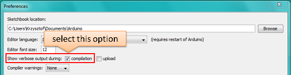
Note: This setting will be required in step 5 below. You can uncheck this setting afterwards.
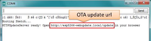
Upload sketch (Ctrl+U). Once done, open Serial Monitor (Ctrl+Shift+M) and check if you see the following message displayed, that contains url for OTA update.
Note: Such message will be shown only after module successfully joins network and is ready for an OTA upload. Please remember about resetting the module once after serial upload as discussed in chapter Arduino IDE, step 3.
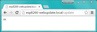
Now open web browser and enter the url provided on Serial Monitor, i.e.
http://esp8266-webupdate.local/update. Once entered, browser should display a form like below that has been served by your module. The form invites you to choose a file for update.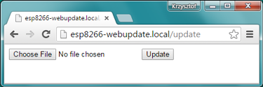
Note: If entering
http://esp8266-webupdate.local/updatedoes not work, try replacingesp8266-webupdatewith module’s IP address. For example, if your module IP is192.168.1.100then url should behttp://192.168.1.100/update. This workaround is useful in case the host software installed in step 1 does not work. If still nothing works and there are no clues on the Serial Monitor, try to diagnose issue by opening provided url in Google Chrome, pressing F12 and checking contents of “Console” and “Network” tabs. Chrome provides some advanced logging on these tabs.To obtain the file, navigate to directory used by Arduino IDE to store results of compilation. You can check the path to this file in compilation log shown in IDE debug window as marked below.
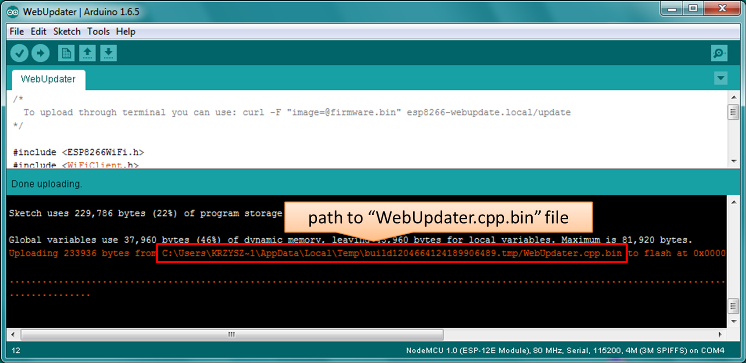
Now press “Choose File” in web browser, go to directory identified in step 5 above, find the file “WebUpdater.cpp.bin” and upload it. If upload is successful, you will see “OK” on web browser like below.
Module will reboot that should be visible on Serial Monitor:
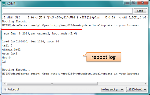
Just after reboot you should see exactly the same message
HTTPUpdateServer ready! Open http://esp8266-webupdate.local/update in your browserlike in step 3. This is because module has been loaded again with the same code – first using serial port, and then using OTA.
Once you are comfortable with this procedure, go ahead and modify WebUpdater.ino sketch to print some additional messages, compile it, locate new binary file and upload it using web browser to see entered changes on a Serial Monitor.
You can also add OTA routines to your own sketch following guidelines in Implementation Overview above. If this is done correctly, you should be always able to upload new sketch over the previous one using a web browser.
In case OTA update fails dead after entering modifications in your sketch, you can always recover module by loading it over a serial port. Then diagnose the issue with sketch using Serial Monitor. Once the issue is fixed try OTA again.
HTTP Server
ESPhttpUpdate class can check for updates and download a binary file from HTTP web server. It is possible to download updates from every IP or domain address on the network or Internet.
Requirements
- web server
Arduino code
Simple updater
Simple updater downloads the file every time the function is called.
ESPhttpUpdate.update("192.168.0.2", 80, "/arduino.bin");
Advanced updater
Its possible to point update function to a script at the server. If version string argument is given, it will be sent to the server. Server side script can use this to check if update should be performed.
Server side script can respond as follows: - response code 200, and send the firmware image, - or response code 304 to notify ESP that no update is required.
t_httpUpdate_return ret = ESPhttpUpdate.update("192.168.0.2", 80, "/esp/update/arduino.php", "optional current version string here");
switch(ret) {
    case HTTP_UPDATE_FAILED:
        Serial.println("[update] Update failed.");
        break;
    case HTTP_UPDATE_NO_UPDATES:
        Serial.println("[update] Update no Update.");
        break;
    case HTTP_UPDATE_OK:
        Serial.println("[update] Update ok."); // may not called we reboot the ESP
        break;
}
Server request handling
Simple updater
For the simple updater the server only needs to deliver the binary file for update.
Advanced updater
For advanced update management a script needs to run at the server side, for example a PHP script. At every update request the ESP sends some information in HTTP headers to the server.
Example header data:
[HTTP_USER_AGENT] => ESP8266-http-Update
[HTTP_X_ESP8266_STA_MAC] => 18:FE:AA:AA:AA:AA
[HTTP_X_ESP8266_AP_MAC] => 1A:FE:AA:AA:AA:AA
[HTTP_X_ESP8266_FREE_SPACE] => 671744
[HTTP_X_ESP8266_SKETCH_SIZE] => 373940
[HTTP_X_ESP8266_SKETCH_MD5] => a56f8ef78a0bebd812f62067daf1408a
[HTTP_X_ESP8266_CHIP_SIZE] => 4194304
[HTTP_X_ESP8266_SDK_VERSION] => 1.3.0
[HTTP_X_ESP8266_VERSION] => DOOR-7-g14f53a19
With this information the script now can check if an update is needed. It is also possible to deliver different binaries based on the MAC address for example.
Script example:
<?PHP

header('Content-type: text/plain; charset=utf8', true);

function check_header($name, $value = false) {
    if(!isset($_SERVER[$name])) {
        return false;
    }
    if($value && $_SERVER[$name] != $value) {
        return false;
    }
    return true;
}

function sendFile($path) {
    header($_SERVER["SERVER_PROTOCOL"].' 200 OK', true, 200);
    header('Content-Type: application/octet-stream', true);
    header('Content-Disposition: attachment; filename='.basename($path));
    header('Content-Length: '.filesize($path), true);
    header('x-MD5: '.md5_file($path), true);
    readfile($path);
}

if(!check_header('HTTP_USER_AGENT', 'ESP8266-http-Update')) {
    header($_SERVER["SERVER_PROTOCOL"].' 403 Forbidden', true, 403);
    echo "only for ESP8266 updater!\n";
    exit();
}

if(
    !check_header('HTTP_X_ESP8266_STA_MAC') ||
    !check_header('HTTP_X_ESP8266_AP_MAC') ||
    !check_header('HTTP_X_ESP8266_FREE_SPACE') ||
    !check_header('HTTP_X_ESP8266_SKETCH_SIZE') ||
    !check_header('HTTP_X_ESP8266_SKETCH_MD5') ||
    !check_header('HTTP_X_ESP8266_CHIP_SIZE') ||
    !check_header('HTTP_X_ESP8266_SDK_VERSION')
) {
    header($_SERVER["SERVER_PROTOCOL"].' 403 Forbidden', true, 403);
    echo "only for ESP8266 updater! (header)\n";
    exit();
}

$db = array(
    "18:FE:AA:AA:AA:AA" => "DOOR-7-g14f53a19",
    "18:FE:AA:AA:AA:BB" => "TEMP-1.0.0"
);

if(!isset($db[$_SERVER['HTTP_X_ESP8266_STA_MAC']])) {
    header($_SERVER["SERVER_PROTOCOL"].' 500 ESP MAC not configured for updates', true, 500);
}

$localBinary = "./bin/".$db[$_SERVER['HTTP_X_ESP8266_STA_MAC']].".bin";

// Check if version has been set and does not match, if not, check if
// MD5 hash between local binary and ESP8266 binary do not match if not.
// then no update has been found.
if((!check_header('HTTP_X_ESP8266_SDK_VERSION') && $db[$_SERVER['HTTP_X_ESP8266_STA_MAC']] != $_SERVER['HTTP_X_ESP8266_VERSION'])
    || $_SERVER["HTTP_X_ESP8266_SKETCH_MD5"] != md5_file($localBinary)) {
    sendFile($localBinary);
} else {
    header($_SERVER["SERVER_PROTOCOL"].' 304 Not Modified', true, 304);
}

header($_SERVER["SERVER_PROTOCOL"].' 500 no version for ESP MAC', true, 500);
Stream Interface
TODO describe Stream Interface
The Stream Interface is the base for all other update modes like OTA, http Server / client.
Updater class
Updater is in the Core and deals with writing the firmware to the flash, checking its integrity and telling the bootloader (eboot) to load the new firmware on the next boot.
Note: The bootloader command will be stored into the first 128 bytes of user RTC memory, then it will be retrieved by eboot on boot. That means that user data present there will be lost (per discussion in #5330).
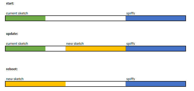
Update process - memory view
- The new sketch will be stored in the space between the old sketch and the spiff.
- on the next reboot the “eboot” bootloader check for commands.
- the new sketch is now copied “over” the old one.
- the new sketch is started.