Reference
Interrupts
Interrupts can be used on the ESP8266, but they must be used with care and have several limitations:
- Interrupt callback functions must be in IRAM, because the flash may be
in the middle of other operations when they occur. Do this by adding
the
ICACHE_RAM_ATTRattribute on the function definition. If this attribute is not present, the sketch will crash when it attempts toattachInterruptwith an error message.
ICACHE_RAM_ATTR void gpio_change_handler(void *data) {...
- Interrupts must not call
delay()oryield(), or call any routines which internally usedelay()oryield()either. - Long-running (>1ms) tasks in interrupts will cause instabilty or crashes.
WiFi and other portions of the core can become unstable if interrupts
are blocked by a long-running interrupt. If you have much to do, you can
set a volatile global flag that your main
loop()can check each pass or use a scheduled function (which will be called outside of the interrupt context when it is safe) to do long-running work. - Memory operations can be dangerous and should be avoided in interrupts.
Calls to
newormallocshould be minimized because they may require a long running time if memory is fragmented. Calls toreallocandfreemust NEVER be called. Using any routines or objects which callfreeorreallocthemselves is also forbidden for the same reason. This means thatString,std::string,std::vectorand other classes which use contiguous memory that may be resized must be used with extreme care (ensuring strings aren’t changed, vector elements aren’t added, etc.).
Digital IO
Pin numbers in Arduino correspond directly to the ESP8266 GPIO pin
numbers. pinMode, digitalRead, and digitalWrite functions
work as usual, so to read GPIO2, call digitalRead(2).
Digital pins 0—15 can be INPUT, OUTPUT, or INPUT_PULLUP. Pin
16 can be INPUT, OUTPUT or INPUT_PULLDOWN_16. At startup,
pins are configured as INPUT.
Pins may also serve other functions, like Serial, I2C, SPI. These functions are normally activated by the corresponding library. The diagram below shows pin mapping for the popular ESP-12 module.
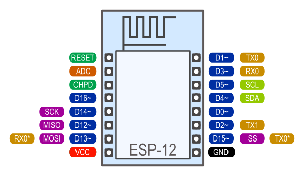
Pin Functions
Digital pins 6—11 are not shown on this diagram because they are used to connect flash memory chip on most modules. Trying to use these pins as IOs will likely cause the program to crash.
Note that some boards and modules (ESP-12ED, NodeMCU 1.0) also break out pins 9 and 11. These may be used as IO if flash chip works in DIO mode (as opposed to QIO, which is the default one).
Pin interrupts are supported through attachInterrupt,
detachInterrupt functions. Interrupts may be attached to any GPIO
pin, except GPIO16. Standard Arduino interrupt types are supported:
CHANGE, RISING, FALLING. ISRs need to have
ICACHE_RAM_ATTR before the function definition.
Analog input
ESP8266 has a single ADC channel available to users. It may be used either to read voltage at ADC pin, or to read module supply voltage (VCC).
To read external voltage applied to ADC pin, use analogRead(A0).
Input voltage range of bare ESP8266 is 0 — 1.0V, however some many
boards may implement voltage dividers. To be on the safe side, <1.0V
can be tested. If e.g. 0.5V delivers values around ~512, then maximum
voltage is very likely to be 1.0V and 3.3V may harm the ESP8266.
However values around ~150 indicates that the maximum voltage is
likely to be 3.3V.
To read VCC voltage, use ESP.getVcc() and ADC pin must be kept
unconnected. Additionally, the following line has to be added to the
sketch:
ADC_MODE(ADC_VCC);
This line has to appear outside of any functions, for instance right
after the #include lines of your sketch.
Analog output
analogWrite(pin, value) enables software PWM on the given pin. PWM
may be used on pins 0 to 16. Call analogWrite(pin, 0) to disable PWM
on the pin. value may be in range from 0 to PWMRANGE, which is
equal to 1023 by default. PWM range may be changed by calling
analogWriteRange(new_range).
PWM frequency is 1kHz by default. Call
analogWriteFreq(new_frequency) to change the frequency. Valid values
are from 100Hz up to 40000Hz.
The ESP doesn’t have hardware PWM, so the implementation is by software. With one PWM output at 40KHz, the CPU is already rather loaded. The more PWM outputs used, and the higher their frequency, the closer you get to the CPU limits, and the less CPU cycles are available for sketch execution.
Timing and delays
millis() and micros() return the number of milliseconds and
microseconds elapsed after reset, respectively.
delay(ms) pauses the sketch for a given number of milliseconds and
allows WiFi and TCP/IP tasks to run. delayMicroseconds(us) pauses
for a given number of microseconds.
Remember that there is a lot of code that needs to run on the chip
besides the sketch when WiFi is connected. WiFi and TCP/IP libraries get
a chance to handle any pending events each time the loop() function
completes, OR when delay is called. If you have a loop somewhere in
your sketch that takes a lot of time (>50ms) without calling delay,
you might consider adding a call to delay function to keep the WiFi
stack running smoothly.
There is also a yield() function which is equivalent to
delay(0). The delayMicroseconds function, on the other hand,
does not yield to other tasks, so using it for delays more than 20
milliseconds is not recommended.
Serial
Serial object works much the same way as on a regular Arduino. Apart
from hardware FIFO (128 bytes for TX and RX) Serial has
additional 256-byte TX and RX buffers. Both transmit and receive is
interrupt-driven. Write and read functions only block the sketch
execution when the respective FIFO/buffers are full/empty. Note that
the length of additional 256-bit buffer can be customized.
Serial uses UART0, which is mapped to pins GPIO1 (TX) and GPIO3
(RX). Serial may be remapped to GPIO15 (TX) and GPIO13 (RX) by calling
Serial.swap() after Serial.begin. Calling swap again maps
UART0 back to GPIO1 and GPIO3.
Serial1 uses UART1, TX pin is GPIO2. UART1 can not be used to
receive data because normally it’s RX pin is occupied for flash chip
connection. To use Serial1, call Serial1.begin(baudrate).
If Serial1 is not used and Serial is not swapped - TX for UART0
can be mapped to GPIO2 instead by calling Serial.set_tx(2) after
Serial.begin or directly with
Serial.begin(baud, config, mode, 2).
By default the diagnostic output from WiFi libraries is disabled when
you call Serial.begin. To enable debug output again, call
Serial.setDebugOutput(true). To redirect debug output to Serial1
instead, call Serial1.setDebugOutput(true).
You also need to use Serial.setDebugOutput(true) to enable output
from printf() function.
The method Serial.setRxBufferSize(size_t size) allows to define the
receiving buffer depth. The default value is 256.
Both Serial and Serial1 objects support 5, 6, 7, 8 data bits,
odd (O), even (E), and no (N) parity, and 1 or 2 stop bits. To set the
desired mode, call Serial.begin(baudrate, SERIAL_8N1),
Serial.begin(baudrate, SERIAL_6E2), etc.
A new method has been implemented on both Serial and Serial1 to
get current baud rate setting. To get the current baud rate, call
Serial.baudRate(), Serial1.baudRate(). Return a int of
current speed. For example
// Set Baud rate to 57600
Serial.begin(57600);

// Get current baud rate
int br = Serial.baudRate();

// Will print "Serial is 57600 bps"
Serial.printf("Serial is %d bps", br);
Serial and Serial1 objects are both instances of the
HardwareSerial class.To detect an unknown baudrate of data coming into Serial use Serial.detectBaudrate(time_t timeoutMillis). This method tries to detect the baudrate for a maximum of timeoutMillis ms. It returns zero if no baudrate was detected, or the detected baudrate otherwise. The detectBaudrate() function may be called before Serial.begin() is called, because it does not need the receive buffer nor the SerialConfig parameters.
The uart can not detect other parameters like number of start- or stopbits, number of data bits or parity.
The detection itself does not change the baudrate, after detection it should be set as usual using Serial.begin(detectedBaudrate).
Detection is very fast, it takes only a few incoming bytes.
SerialDetectBaudrate.ino is a full example of usage.
Progmem
The Program memory features work much the same way as on a regular
Arduino; placing read only data and strings in read only memory and
freeing heap for your application. The important difference is that on
the ESP8266 the literal strings are not pooled. This means that the same
literal string defined inside a F("") and/or PSTR("") will take
up space for each instance in the code. So you will need to manage the
duplicate strings yourself.
There is one additional helper macro to make it easier to pass
const PROGMEM strings to methods that take a __FlashStringHelper
called FPSTR(). The use of this will help make it easier to pool
strings. Not pooling strings…
String response1;
response1 += F("http:");
...
String response2;
response2 += F("http:");
using FPSTR would become…
const char HTTP[] PROGMEM = "http:";
...
{
    String response1;
    response1 += FPSTR(HTTP);
    ...
    String response2;
    response2 += FPSTR(HTTP);
}
C++
About C++ exceptions,
operator new, and Exceptions menu optionThe C++ standard says the following about the
newoperator behavior when encountering heap shortage (memory full):- has to throw a
std::bad_allocC++ exception when they are enabled - will
abort()otherwise
There are several reasons for the first point above, among which are:
- guarantee that the return of new is never a
nullptr - guarantee full construction of the top level object plus all member subobjects
- guarantee that any subobjects partially constructed get destroyed, and in the correct order, if oom is encountered midway through construction
When C++ exceptions are disabled, or when using
new(nothrow), the above guarantees can’t be upheld, so the second point (abort()) above is the onlystd::c++viable solution.Historically in Arduino environments,
newis overloaded to simply return the equivalentmalloc()which in turn can returnnullptr.This behavior is not C++ standard, and there is good reason for that: there are hidden and very bad side effects. The class and member constructors are always called, even when memory is full (
this == nullptr). In addition, the memory allocation for the top object could succeed, but allocation required for some member object could fail, leaving construction in an undefined state. So the historical behavior of Ardudino’snew, when faced with insufficient memory, will lead to bad crashes sooner or later, sometimes unexplainable, generally due to memory corruption even when the returned value is checked and managed. Luckily on esp8266, trying to update RAM near address 0 will immediately raise an hardware exception, unlike on other uC like avr on which that memory can be accessible.As of core 2.6.0, there are 3 options: legacy (default) and two clear cases when
newencounters oom:newreturnsnullptr, with possible bad effects or immediate crash when constructors (called anyway) initialize members (exceptions are disabled in this case)- C++ exceptions are disabled:
newcallsabort()and will “cleanly” crash, because there is no way to honor memory allocation or to recover gracefully. - C++ exceptions are enabled:
newthrows astd::bad_allocC++ exception, which can be caught and handled gracefully. This assures correct behavior, including handling of all subobjects, which guarantees stability.
- has to throw a
New optional allocator
arduino_newA new optional global allocator is introduced with a different semantic:
- never throws exceptions on oom
- never calls constructors on oom
- returns nullptr on oom
It is similar to arduino
newsemantic without side effects (except when parent constructors, or member constructors usenew).Syntax is slightly different, the following shows the different usages:
// with new:

SomeClass* sc = new SomeClass(arg1, arg2, ...);
delete sc;

SomeClass* scs = new SomeClass[42];
delete [] scs;

// with arduino_new:

SomeClass* sc = arduino_new(SomeClass, arg1, arg2, ...);
delete sc;

SomeClass* scs = arduino_newarray(SomeClass, 42);
delete [] scs;